
Failure phenomenon
A 2012faw Audi A6L C6 2.0T sedan, equipped with BPJ engine, automatic air conditioning, the owner reflects that when the air conditioner is turned on, the central air outlet does not show wind, and the air outlet on both sides of the instrument panel is normal.
Fault diagnosis and remove
1. Verify the fault, open the air door of the central air outlet, set the automatic mode or manual mode, and the central air outlet is out of wind. Audi A6 C6 is equipped with automatic air conditioner, and each temperature air baffle and air duct air baffle are driven by servo motor. Because the central air outlet is out of wind and the air outlets on both sides are normal, the possible causes of the failure include: Central air baffle stuck, central air plate servo motor V102 or potentiometer G138 failure, air conditioning control unit J255 failure, related line failure.
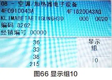
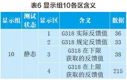
2. Use VAS5052 to detect 08 the air conditioning control unit J255 has no fault code storage, and focus on checking the central air baffle servo motor V102 and the central air baffle, reading the Display Group 10 (figure 66) and displaying the V102 data. However, the meaning of each area is not marked on the display screen. The meaning and data of each area are shown in Table 6, and the open air plate is closed on the data table.
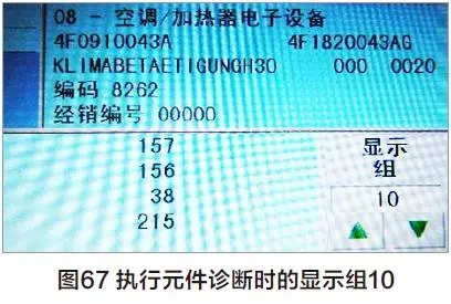
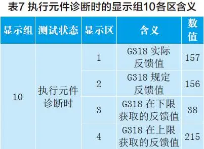
3. Perform component diagnosis with VAS5052, rotate V102, read Display Group 10 (Figure 67), and display V102 data. However, the meaning of each area is not marked on the display screen. The meaning and data of each area are shown in Table 7, and the open air plate is in the open position on the data table.
4. Through the above tests, it is suspected that the central air baffle is stuck, but the check air baffle is not stuck. After installing V102, first drive it to the open position, then turn on the air conditioner. After the central air outlet is out of the wind for a short time, the wind will not flow soon. The actual feedback value of G138 from the data flow analysis potentiometer is consistent with the actual position of air baffle.
5. According to the circuit diagram (Figure 68), pull off the J255 plug, apply temporary voltage to B15 and B16 pins on the wiring harness side, V102 rotates normally, switch the voltage polarity, V102 is reversing rotation, this indicates that V102 has no exception.

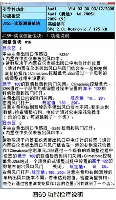
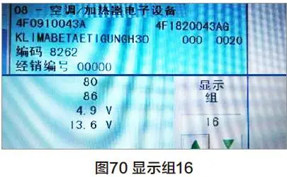
6. After testing, it is confirmed that V102, G138 and lines are normal. At this time, J255 is suspected of failure, but it is not certain. Carefully read the function check instructions on the VAS5052 (figure 69), read the Display Group 16 (Figure 70), and display the V102 air plate position voltage signal. Both tests are closed.
7. Through the analysis of the above data, it was judged that G138 sent an error signal to J255, and decided to remove the central air outlet to check potentiometer G138. It was found that the central air baffle missed the installation of the drive shaft, so that G138 was not activated. Because the drive shaft is an accessory of the central air outlet, replace the central air outlet, the test air outlet is normal, and the fault is eliminated.
Failure point: Central air baffle leakage drive shaft.
Maintenance summary
Because the central air baffle leaks the drive shaft, the central air baffle position signal cannot be transmitted.