
◆ Wen/Henan Wang Liangbin
This article will explain the structure and composition of the intake system of the electronic control engine and the functions of its main components. In addition, the article will also analyze in detail the influence of vacuum leakage in each section of the intake system on the engine.
I. Electronic control engine intake system
1.L-type system and D-type system
Modern car electronic control device engine uses the fast-moving position of piston to form vacuum suction, and uses the propelling effect of atmospheric pressure (the external pressure of supercharged engine is more than one atmospheric pressure) to suck air pump into the cylinder to complete the suction process. In the process of air flowing through the intake pipe, the heavy resistance formed by the structural components and functional components of the intake pipe must be overcome, and a higher speed must be formed within a very limited time, enter the cylinder as much as possible. At the same time, relevant functional components need to clean, measure and control the quantity of intake air.
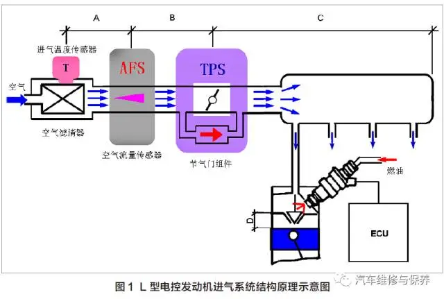
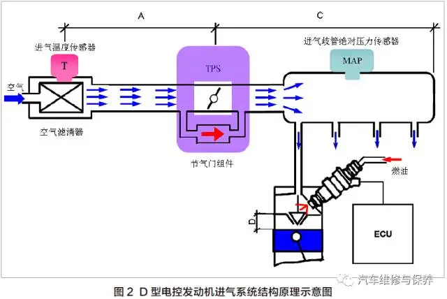
The air filter is cleaned to intake air. The control of the amount of air entering is completed by the throttle gate and the idling control device on the bypass channel (the electronic throttle gate has no bypass channel). There are two methods for measuring air volume: direct and indirect. Direct method is to use the air flow sensor (AFS) to directly measure the air flow so as to carry out fuel quantification, which is called L-type electronic control engine, and its electronic control system is simply called L-type system, as shown in Figure 1. Indirect method is to measure intake manifold absolute pressure through intake manifold absolute pressure sensor (MAP), and then indirectly determine the intake air volume in combination with the engine speed to carry out fuel quantitative, which is called D-type electronic control engine, its electronic control system is simply called D-type system, as shown in figure 2.
2. Air filter
The air passes through the microporous air gap of the air filter element to filter out the particulate impurities suspended in the air, reducing the early wear of the cylinder, piston, piston ring, Valve and valve seat, at the same time, the measurement and control accuracy of functional components on the air intake system also need relatively clean air to ensure that the Clean Air also keeps the air intake pipeline clean, smooth and effective for a long time.
3. Intake air temperature sensor
There is a thermistor of negative temperature coefficient in the intake air temperature sensor, which is connected in series with a fixed resistor in the engine electronic control unit (ECU) to form voltage division circuit. ECU provides voltage division circuit with 5V power supply. The inlet temperature rises/falls, the resistance value of thermistor decreases/rises, and the voltage on thermistor also decreases/rises. The voltage on thermistor has a one-to-one correspondence with the intake temperature, so ECU can infer the intake temperature according to the voltage on thermistor. D-type system and volume flow AFS to determine the air volume need to be corrected by the intake air temperature sensor signal. The intake air temperature sensor is usually installed on the hose behind the air filter, some are integrated in AFS or MAP, and some are installed on the air filter housing.
4. Air flow sensor (AFS)
AFS is usually set after the air filter and before throttle gate. When the air flows through AFS at high speed, AFS converts the air flow into an electrical signal (voltage or frequency) and sends it to ECU. The fuel quantitative control system of ECU combines the engine speed and cylinder number according to the measured air flow, calculate the amount of air sucked in each cycle of each cylinder, and then complete the configuration of mixed steam air-fuel ratio (A/F) by controlling the injection pulse width of the injector and matching the corresponding amount of fuel per cycle. AFS signal is the engine load information, which is mainly used for fuel quantity and ignition timing control.
Hot wire and thermal mode AFS can directly measure mass air flow, directly used in A/F configuration, and the measurement results are not affected by air pressure, and the flow resistance is small, the measurement accuracy is high, and the performance is excellent, it has been widely used. Vane type and Carmen Vortex type AFS measure volume air flow. After measuring volume air flow, it must be multiplied by air density and converted into mass air flow before it can be used in A/F configuration, however, air density is related to temperature and pressure, and the intake temperature and pressure need to be measured by corresponding sensors. These intermediate links will bring errors and affect the final accuracy. Blade and Carmen vortex AFS are used in early electronic control engines and have been eliminated.
5. Intake manifold absolute pressure sensor (MAP)
In early engines, MAP was usually made into a component installed on ECU or on cylinder head or cylinder block near intake manifold, and connected to intake manifold with vacuum hose. Now the engine directly installs MAP on the intake manifold, eliminating the vacuum hose to avoid possible vacuum leakage. This design is the most reasonable.
The amount of air sucked in each cycle of each cylinder has a definite functional relationship with intake manifold absolute pressure and engine speed. The functional relationship of the established engine in the standard state is obtained through experiments in advance, this function relationship is pre-stored in ECU. In the actual operation of the engine, according to the measured intake manifold absolute pressure and the engine speed, the corresponding amount of air sucked in each cycle of each cylinder is checked, then correct according to the current intake temperature, and then complete the configuration of A/F by controlling the injection pulse width of the injector with the corresponding fuel quantity per cycle. MAP signal is the load information of the engine. As the load information, besides mainly used for fuel quantitative and ignition timing control, some engine electronic control systems are also used for fault self-diagnosis system and exhaust gas recirculation (EGR) the feedback signal.
6. Throttle body assembly
Throttle body assembly is an important component of the intake system. In addition to completing the intake control and Lac idle air control, it also converts the process of controlling the intake into electrical signals and transmits them to ECU. Throttle body assembly is equipped with throttle gate, throttle gate position sensor (TPS) and idling control device. During the driving process of the car, the output power of the engine needs to be adjusted in real time to meet the requirements of the change of the driving load of the car. By changing the size of throttle percentage, the amount of air inhaled is controlled, so as to adjust the output power of the engine, real-time matching between engine output power and driving load is realized.
The size of throttle percentage is measured by TPS. TPS is a kind of angle potentiometer. The potentiometer axis rotates equally with the throttle shaft, converting the throttle gate angle (opening degree) into voltage signal to ECU, providing ECU with load range (full load, partial load, idle speed) information, ECU can also generate excessive working condition changes (urgent or slow acceleration working condition, urgent or slow deceleration working condition) information. TPS signal is not only engine load information, but also vehicle working condition information.
TPS information is mainly used for the optimization of fuel quantitative control and ignition timing control under excessive working conditions. TPS information is one of the load information. When other load information sensors (AFS or MAP) of the electronic control system fail, TPS information replaces the load information to maintain the basic operation of the car. In addition, TPS signal is also one of the main control signals of automatic transmission shift rule.
II. Influence of vacuum leakage of intake system on engine
For naturally aspirated multi-cylinder engines, the piston of each cylinder is in the fast speed position of suction stroke, and the intake system is not smooth, so the air cannot completely replenish the space within a limited time, this is how the vacuum environment of the intake system is formed.
The air filter has resistance to air flow. After the air filter, a certain degree of vacuum has been formed. Throttle gate has a greater barrier to air flow, and after throttle gate, the degree of vacuum is higher. Exhaust has the largest barrier to air flow, the vacuum degree in the cylinder is the highest. The vacuum degree of the air intake system is just like this and goes up step by step. Generally, if there is no special explanation, the engine vacuum degree refers to the vacuum degree in the period before throttle gate after exhaust, that is, intake manifold vacuum degree. The vacuum leakage of the intake system described herein refers to the entire intake system, including cylinders.
The air entering the cylinder must be filtered through the air filter, AFS or MAP metering and throttle gate control ", the air or gas entering the cylinder without any link is" illegal "gas. As for the gas introduced into the intake system by EGR system, crankcase forced ventilation (PCV) system and fuel evaporation emission control (EVAP) system, it has been included in ECU control system to compensate, and it is not included in this column. In the practical application of the engine, due to the problems such as the rupture of the intake pipe, the damage of the vacuum hose, the aging of the seal and so on, part of the gas is not filtered or is not measured or is not controlled or even directly into the cylinder, all kinds of vacuum leakage of intake system will affect the normal operation of the engine, and in severe cases, the engine will not work. The degree of influence of vacuum leakage of intake system on the engine varies depending on the leakage location, leakage volume and type of engine electronic control system.
For the convenience of discussion, the intake system is divided into four sections A, B, C and D as marked in Figure 1 and Figure 2. After the air filter to AFS is A segment, after AFS to throttle gate is B segment, after throttle gate to exhaust is C segment, after exhaust to the piston plane is D segment. Obviously, the D-type system does not have Segment B, but only segments A, C and D.
1. The influence of section A vacuum leakage on the engine
Section A vacuum leakage, "illegal" gas is controlled by throttle gate and measured by AFS or MAP, for L-type system and D-type system (after air filter to throttle gate is Section A) the impact is the same. In the early stage, it will not have obvious failure impact on engine operation, and long-term operation will do great harm. Its harm is reflected in two aspects.
On the one hand, the dust carried by the unfiltered air is sucked into the intake system, which pollutes throttle gate and the combustion chamber, accelerates the wear of the cylinder, and accelerates the blocking of the air vent, such as the blocking of the three-way device. Obviously, this is a gradual gradual change from quantitative change to qualitative change. In the early stage, there may be no noise and no abnormal phenomenon. As the accumulation of days and months, throttle gate is covered by foreign matter. The opening of throttle gate is seriously out of balance with TPS signal. The foreign matter occupying in the combustion chamber makes the actual compression ratio greater than the designed compression ratio, and the cylinder sealing performance decreases, the three-way device is blocked. It can be seen that no matter which one, the engine cannot operate normally. Vacuum leakage in Sections B, C and D will also bring such harm.
On the other hand, this part of "illegal" gas easily enters the intake system without air filter filtration resistance, because it does not receive the necessary resistance, theoretically speaking, it will definitely break the original optimal balance control point of the engine control system. Usually, the/F closed-loop control system can compensate, which has little influence on the normal operation of the engine. Some cases show that when the vacuum leakage of stage A Reaches A degree, some engines will generate idle periodic jitter, while other starting, accelerating and operating conditions are normal.
2. Influence of vacuum leakage in section B on engine
For L-type systems, "illegal" gases are not measured by AFS but are controlled by throttle gate. The vacuum leakage of segment B, the air flow corresponding to AFS signal is smaller than the actual vacuum degree of segment B at present. At present, ECU has a small distortion signal for this AFS signal, and no diagnosis and compensation mechanism is set. ECU knows nothing about this, and still uses AFS as a small distortion signal to quantify fuel according to established procedures. Obviously, the/F preparation is too thin. If the vacuum leakage is small, the/F closed-loop control system can compensate. If the vacuum leakage is large, the adjustment range of the/F closed-loop control system is out, you cannot adjust the sparse A/F back. Too thin A/F causes engine idle instability, weak acceleration, start flameout, tempering and other faults. The self-diagnosis system generates fault codes, usually reporting fault codes such as too thin A/F and bad AFS signals.
3. Influence of C- segment vacuum leakage on engine
For L-type systems, the C- segment vacuum leaks, and illegal gases are neither controlled by throttle gate nor measured by AFS. It directly causes A/F to be too thin, and its harm is as mentioned above. For D-type system, C- segment vacuum leakage, illegal gas is not controlled by throttle gate but measured by MAP. Compared with vacuum leakage before throttle gate, it brings more serious harm to the engine, its harm is reflected in two aspects.
On the one hand, TPS and MAP signals lose the original established one-to-one correspondence, fundamentally destroying the basic control of ECU, causing the engine to deviate from the optimal point of operation, which is manifested as power decline, hidden faults that do not endanger the driving of cars, such as rising fuel consumption.
On the other hand, idle speed is out of control. The "illegal" gas is not controlled by the lac idle air control system (hereinafter referred to as the idle control system), but is measured normally by MAP. ECU has no knowledge about MAP as a large distortion signal, MAP is still used as a large distortion signal to quantify fuel according to established procedures. Obviously, the/F preparation itself is impeccable, but the increase of mixed steam volume increases the idle speed. If the vacuum leakage is small, the idle control system can adjust to normal idle speed. With the increase of vacuum leakage, the idle control system can not be adjusted back when it is adjusted to the minimum, and the idle speed continues to rise. If ECU does not have the function of slowing down and cutting off oil, idle speed will continue to rise with the increase of vacuum leakage, resulting in the phenomenon of flying. If ECU has the function of slowing down and cutting off oil, when idle speed rises to the speed of cutting off oil, idle speed decreases due to oil cut off. When idle speed falls to the speed of restoring oil supply, idle speed rises due to oil supply, so circulation, the phenomenon of traveling is generated.
4. Influence of D-segment vacuum leakage on engine
The impact of D-segment vacuum leakage on the engine is the most fatal. There are three ways for "illegal" gas to directly invade the cylinder without filtration, metering and control. First, the gap between the piston and the cylinder. Severe wear of piston ring and cylinder, bonding of piston ring and scuffing of cylinder bore will cause gas in crankcase to be directly sucked into cylinder during suction stroke. Secondly, the seal of cylinder gasket. Cylinder gasket looseness, burning loss and punching loss will cause suction stroke air to be directly sucked into the cylinder; Third, exhaust valve sealing surface. Exhaust valve due to carbon deposit and severe wear on the sealing surface, the exhaust gas from the suction stroke will return and be sucked into the cylinder. Once the technical condition of the engine deteriorates to such an extent, it cannot operate at all.
III. Conclusion
1. Establish the concept of large physical space of intake system. From the inlet of the air filter flowing down the river until the combustion chamber is a longitudinal space, the transverse space is those vacuum hose pipes that take the vacuum degree of the engine, and the transverse space extends wherever the vacuum hose goes.
2. Main parts of longitudinal space vacuum leakage. Pipe rupture or damage, pipe connection, intake manifold and cylinder head joint surface, cylinder gasket sealing surface, piston and cylinder friction surface.
3. Vacuum leakage in horizontal space. No matter where the vacuum hose extends, it must be a "dead end", and usually the vacuum actuator (device) is connected at its end. Vacuum leakage caused by damage of vacuum hose and vacuum actuator diaphragm is common. In addition, PCV, EGR, and EVAP systems all have pipelines connected to intake manifold. Any failure or vacuum pipeline damage in the three systems will lead to vacuum leakage.
4. When the engine is running, any air or other gas entering the intake system must be pre-designed by the engine, that is, ECU can control it. Otherwise, it is the vacuum leakage or "illegal" gas of the intake system discussed in this article.
5. The main influence of vacuum leakage of intake system on engine. For the L-type system, the/F is too thin, and the main failure phenomena are: unstable idle speed, weak acceleration, and easy flameout at the beginning. For D-type system, A/F is correctly prepared, and the mixed steam volume does not match the idle working condition. The main failure phenomenon is high idle speed or idle speed traveling.