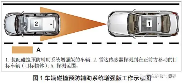
Taking Mercedes-Benz S-Class (222 model) as an example, this paper introduces the enhanced function of Vehicle Collision Prevention assistant system. The enhanced version of the vehicle collision prevention assistant system continuously checks the safe space between car heads of the front car, and sends visual and acoustic warnings to the driver, indicating possible collisions with other vehicles (such as rear-end collision), in the case of imminent collision, the system gives the driver effective braking force support, and even starts part of braking automatically when the driver fails to respond in time, thus greatly reducing the accident risk. The enhanced version of the vehicle collision prevention assistant system is enabled between 7 and 250 km/h (Figure 1).
I. System composition
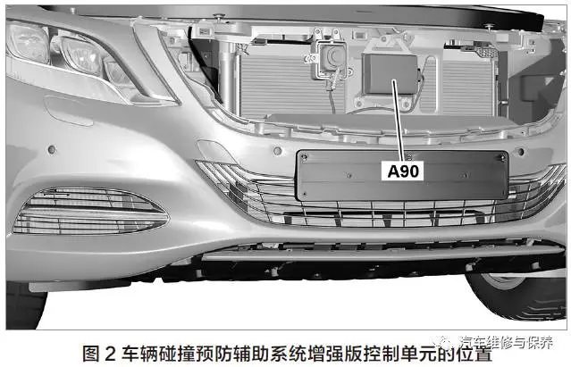
1. Enhanced Control Unit (A90) of vehicle collision prevention assistant system: located in the middle of radiator (Figure 2), it integrates radar sensor and control unit. Radar sensor works based on 25GHz pulse Doppler principle, it is used to measure vehicle distance and vehicle speed independently. The detection range is 0~80m and the detection angle is 30 ° ± 8 °. The control unit receives the information from reading sensors and other control units, comprehensively evaluates the collision risk level, then outputs the request of visual and acoustic warning information, and enables presafe if necessary.
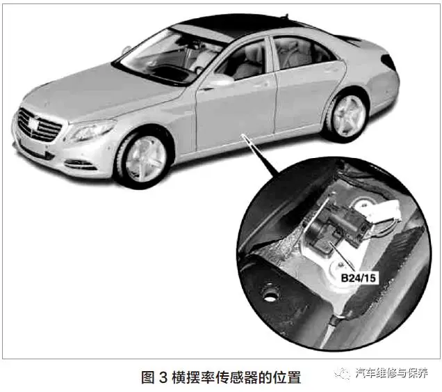
2. Yaw rate, lateral and longitudinal acceleration sensors (B24/15) : Located in the position of the left foot of the vehicle (figure 3), measure the rotational velocity of the wheel along the longitudinal axis, its signal is read by the control unit (N30/4) of the electronic controlled vehicle stable driving system (ESP) through the CAN bus.
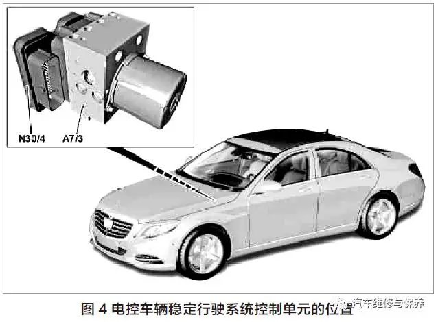
3. Control Unit of stable driving system of electronic controlled vehicle (ESP,N30/4) : Located on the left side of engine compartment (A7/7) in brake booster (Figure 4), it receives the braking request from A90 and actuates the hydraulic unit (A7/3) of the traction system to implement braking, so that the vehicle can slow down or even be completely stationary to avoid collision or reduce collision loss.
4. Instrument: transmit the collision prevention auxiliary system to display the prompt information of possible collision on multifunctional display screen and send a prompt tone to remind the driver. The location of the enhanced component of the vehicle collision prevention auxiliary system is shown in figure 5.

2. Function introduction
The enhanced version of the collision prevention assistance system can assist drivers in two stages.
1. Distance warning stage: A90 calculates the distance between the front car and the time before the collision may occur, and distinguishes the two distance warnings. And the driver cannot actively confirm these warning outputs, and the warning will be canceled only after the condition is lifted.
(1) Static distance warning: under the condition of smooth traffic, if the distance between the car and the front car makes the driving time less than 0.8s, and this dangerous vehicle distance is kept above 3s (for example, when the vehicle speed is 100 km/h and the vehicle distance is about 22.2m), only the static vehicle distance warning is output visually.
(2) collision critical distance warning: If obstacles within the detection range of radar sensors are classified as obstacles with accident danger (collision will occur within 2.6 seconds), the critical distance warning of collision is output through visual and acoustic methods.
2. Brake system intervention stage: the process is divided into two situations according to the driver's response to the warning information.
(1) function sequence of brake assist system: if the driver responds to the distance warning through emergency braking operation, the brake system provides assistance to it so as to make full use of the braking distance with obstacles. If the collision is inevitable, the driver and passenger protection measures will be taken in addition to the intervention of the braking system.
(2) function sequence of automatic partial braking: if the driver does not respond to the warning in case of accident danger, A90 will enable the automatic partial braking function, the required braking torque request is transmitted to the ESP control unit (the maximum deceleration is about 6m/s2) ; In addition, the engine torque reduction request is transmitted to the ME control unit. In this process, A90 considers the following variables at the same time: relative speed with vehicle or obstacle; Distance with vehicle or obstacle.
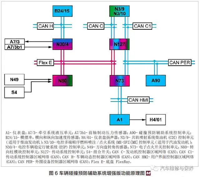
III. System principle
The whole auxiliary system of vehicle collision prevention CAN be deeply understood through Figure 6: CAN bus has bidirectional characteristics, which CAN not only transmit but also receive information; n73, as a central gateway, constitutes the data interface between Flex ray and CAN B. The communication between different CAN networks needs to be completed by means of N73, that is, N73 determines the signal priority and converts it to CAN signal type; the arrow points to the transmission direction or control direction of the representative signal. For example, A90 comprehensively evaluates its own sensors and signals transmitted from the network for analysis to calculate the possible collision risk value, then A90 transmits the brake intervention request to N30/4 through Flex E, and N30/4 touches A7/3 to implement corresponding braking.