

◆ text/Jiangsu Wang Guang Wu Shulong
Failure phenomenon
A 2012 third-generation Toyota Prius (ZVW30) hybrid vehicle with an engine model of 5ZR-FXE and a mileage of 69,000km. According to the driver's report, the engine cannot be started by itself, and the engine fault warning light, VSC warning light, triangle warning light are lit at the same time.
Fault diagnosis and remove
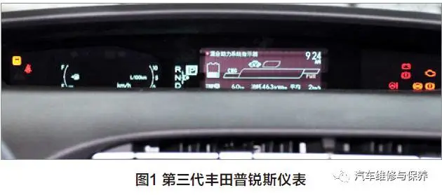
First of all, confirm the fault, press the brake pedal, press the start button, the "READY" indicator light on the instrument will light up, and press the accelerator pedal at the P-block position, and the engine will not start. Attempts to put the engine into maintenance mode cannot be successful after many attempts. The energy display on multifunctional display screen shows that the HV battery has been consumed to the limit, and the purple battery consumption indicator is flashing (Figure 1). This indicates that the engine cannot be started by itself, and there is no problem of manual operation.
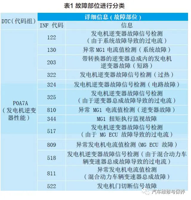
Follow the principle of easy first and difficult later, and perform circuit inspection first according to the troubleshooting process: Use the fault diagnosis equipment to connect to DLC3, read the fault code and display the P0A7A-324 fault code. The 5-digit code used by the hybrid system DTC is different from that used by other systems (such as the engine system). Use 5-digit codes and INF codes to classify fault locations, as shown in Table 1. Troubleshooting is not possible without detailed information (INF code).
Therefore, according to the INF code, there are different troubleshooting steps in the repair manual. If the generator inverter is overheated, there is a circuit fault or an internal short circuit, the inverter transmits the information to MG ECU through the generator inverter fault signal line and records DTC P0A7A-324. According to the analysis, the possible fault locations are as follows:
● inverter cooling system;
● cooling fan system;
● inverter pump assembly;
● inverter assembly with converter;
● hybrid vehicle transmission Bridge Assembly;
● generator high voltage cable;
● Motor high voltage cable;
● wiring harness or connector;
● PCU fuse.
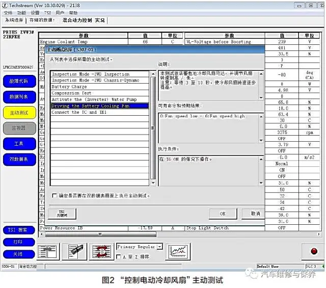
Prius uses a water-cooled inverter, and its coolant inlet and outlet can be easily connected to the radiator to facilitate cooling of the coolant. The coolant is usually similar or the same as the engine coolant. In hybrid electric vehicles, almost all the cooling liquid circuits of such water cooling systems are completely independent of the cooling system of the engine. Coolant is pumped into the inverter from the radiator, but does not touch the working parts of the inverter. The heat sink transfers the heat energy generated by the inverter components to the coolant, and then the coolant flows back to the radiator. With the help of cooling fan, the radiator transfers the heat energy to the surrounding air. If the cooling system of the water-cooled inverter fails, a DTC may be generated, and of course, no DTC may be generated. Therefore, the maintenance technician can put his hand on the coolant pump body to feel whether there is vibration, and verify whether the inverter coolant pump works in this way. However, even if the pump can work normally, it cannot guarantee that the coolant can flow sufficiently, because bubbles or other blockages may also have adverse effects on the normal flow of the coolant. Maintenance Technicians can remove the cover of the expansion tank of the inverter and verify whether the coolant flows normally. On this basis, they can determine whether the coolant circulation is normal. If the inverter overheats, the maintenance technician may check the quality of the coolant when the coolant rate is sufficient. Incorrect cooling liquid or failure to properly mix the cooling liquid with water may lead to Inverter cooling problems. By checking that the coolant volume is normal and the coolant hose has no leakage, use diagnosis equipment to actively test that the "control electric cooling fan" is normal (Figure 2), check that the coolant is not frozen, and eliminate the inverter cooling system, pump Assembly and cooling fan failure.
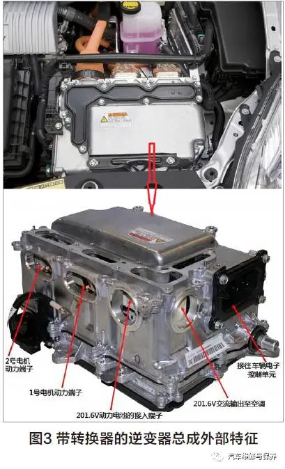
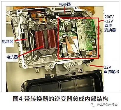
After eliminating the inverter cooling system and its components, it is necessary to further check the inverter assembly with converter. The assembly consists of inverter, booster converter and DC/DC converter and is installed in the engine compartment (figure 3).
When the vehicle is in the power-OFF state (READY is OFF), the capacitor in the inverter (Figure 4) must be electro-discharge treatment through the internal circuit of the inverter itself. Maintenance Technicians should always consult the maintenance information of automobile manufacturers, so as to accurately understand the time required for the discharge of the capacitor of the vehicle, and at the same time to accurately understand the position of the measuring point during the voltage inspection operation.
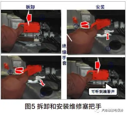
The self-discharge process of Toyota Prius may take 5 to 10 minutes. For maintenance technicians who need to work on the inverter or motor circuit of the vehicle, they must wait until the capacitor has completed the discharge operation, can only work. Therefore, before checking the high-voltage system or disconnecting the inverter assembly low voltage connector with converter, take safety measures, such as wearing insulating gloves and removing the repair plug handle (figure 5) to prevent electric shock. Remove the repair plug handle and put it in the pocket to prevent other technicians from accidentally reconnecting it when we are working on the high-pressure system.
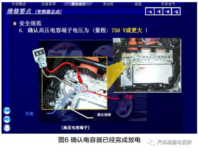
After the maintenance technician removes the repair plug handle, wait for at least 10 minutes before touching any high-voltage connector or terminal, and then check the terminal voltage of the inverter assembly checkpoint with converter, the voltage before starting work should be 0 (figure 6).
After confirming that the capacitor has been discharged, disconnect the negative electrode of the low-voltage battery; Check the transmission Bridge Assembly of the hybrid vehicle (two solution angle transducer) the connection condition of the connector is in good contact with the inverter assembly low voltage connector with converter, and there is no corrosion or looseness.
Disconnect the angle transducer connector D29 from the inverter assembly with converter, reconnect the negative electrode of the low voltage battery, and place the power switch in the ON(IG) position according to the circuit diagram (Fig. 7) check the voltage 0.8V (normal value less than 1V) of each signal line from the generator solution angle transducer to the grounding of the vehicle body, which is normal.
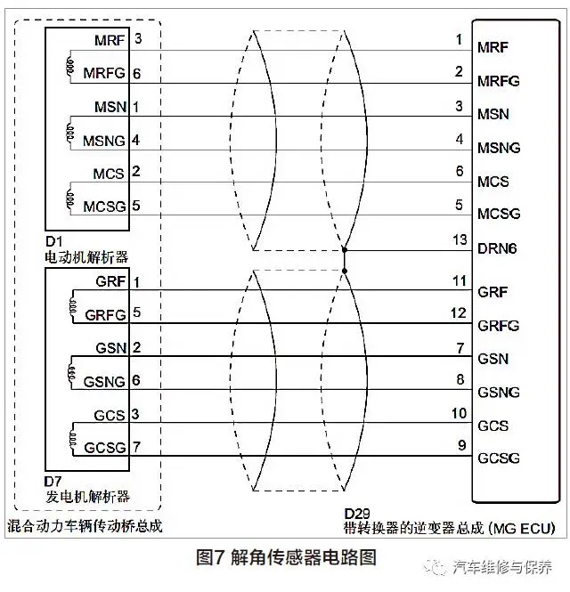
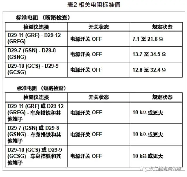
Put the power switch in the OFF position, disconnect the negative electrode of the low-voltage battery, and measure the resistance between the signal lines of the generator angle transducer (GRF-GRFG :8.2 Ω,GSN-GSNG :16.8 Ω,GCS-GCSG :18.6 Ω), generator solution angle transducer the signal line is grounded to the vehicle body and the resistance between the two is infinite. The normal value is shown in Table 2, thus it can be judged that the wiring harness and connector between the generator solution angle transducer and the inverter assembly with converter are normal. It is normal to measure between the inverter assembly with converter and the motor parser in the same way.
Remove the inverter cover from the inverter assembly with converter and disconnect the generator and motor high voltage cables from the inverter assembly with converter (Figure 8). Use milliohm meter to measure the resistance between U, V, W phase and phase without open circuit; Use MEGOHMMETER to measure the insulation resistance between U, V, W phase and body grounding and shielding layer without short circuit; the transmission axle assembly (MG1, MG2) of hybrid vehicle is normal.
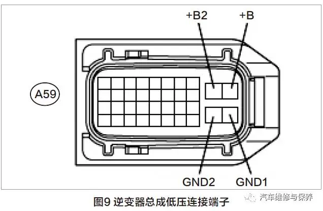
 Disconnect the inverter assembly with converter low voltage connector A59 (Figure 9) and check that the power supply voltage is 12.5V, which is normal.
According to the above inspection results, it is found that the high and low voltage connected wiring harness and plug terminals of the inverter assembly with converter are normal, and there is no problem with the two solution angle transducer and lines on the transmission Bridge assembly of hybrid vehicle, it can be judged that the fault is in the inverter assembly with converter. As the automobile manufacturer stipulates that the inverter assembly with converter is a non-detachable component and can only be replaced. In order to ensure that everything is safe, the inverter assembly with converter can only be tested by using the method of component exchange and the normal driving similar models. After replacement, the faulty car starts normally, and the same fault occurs in another car, it is further proved that the fault occurs inside the inverter assembly with converter. In order to confirm that the fault has been completely eliminated, after several on-the-road test runs, the phenomenon of failure to start disappears, and the vehicle will be delivered to the customer after restoring all the accessories removed by the vehicle.

Having seen this fault case, we must first confirm that the author's diagnosis and repair method for P 0A7A-324 fault codes is correct. According to the guidance of maintenance manual, through the inspection of relevant circuits, the troubleshooting method is adopted to finally eliminate the faults. But for the repair summary of this case, I still want to say a few questions:
1. The basic information of the vehicle should be clearly explained in the article. Toyota's third-generation Prius is equipped with a 5ZRFXE, a 1.8L Atkinson cycle engine, a 42KW generator (MG1) and a 60KW drive motor (MG2). The hybrid power system uses Toyota ths-ii. The function of MG1 is responsible for starting the engine. After the engine is started, the engine drives the operation to generate electricity. The power can be supplied to the vehicle driven by MG2, and MG1 adjusts the engine speed to output torque in the optimal fuel economy area. MG2 can be powered by power storage battery or MG1 to drive the vehicle, and when the vehicle slows down or brakes, it is converted into a generator to run for energy recovery.
2. Hybrid vehicles are highly electromechanical integrated vehicles. When a fault occurs, the cause of the fault should be judged according to the data flow of the vehicle operation. When the P0A7A fault code is stored, there will be freeze-frame data, which will record the abnormal data of the system during the fault occurrence period, for example, the working state, working temperature, output voltage, current and frequency of MG1 inverter. The output signal of the angle transducer is solved. DC-DC the working parameters of supercharger, the working state parameters of MG1 motor, whether the engine starts, etc. can be viewed through intelligent diagnosis equipment to help analyze faults. Similarly, the comparison between the data flow during the operation of THS-Ⅱ system and the standard data under this working condition is also a reference for the data comparison of fault analysis. For this reason, I give the same model as the car. When the power switch is turned on and the "READY" indicator light is on, the standard data of vehicle operation is shown in Figures 10, 11 and 12.
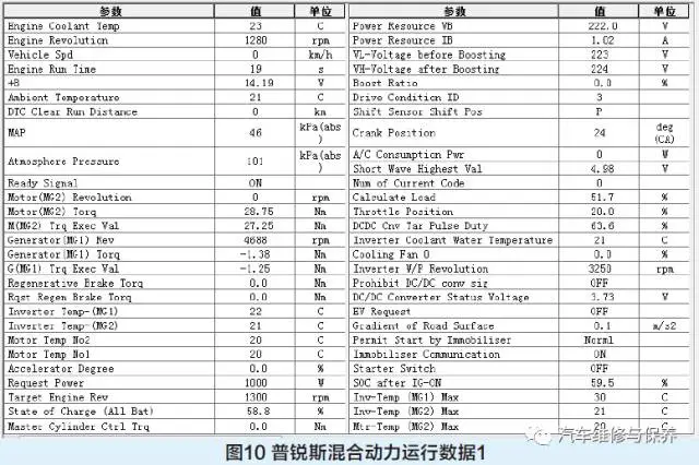
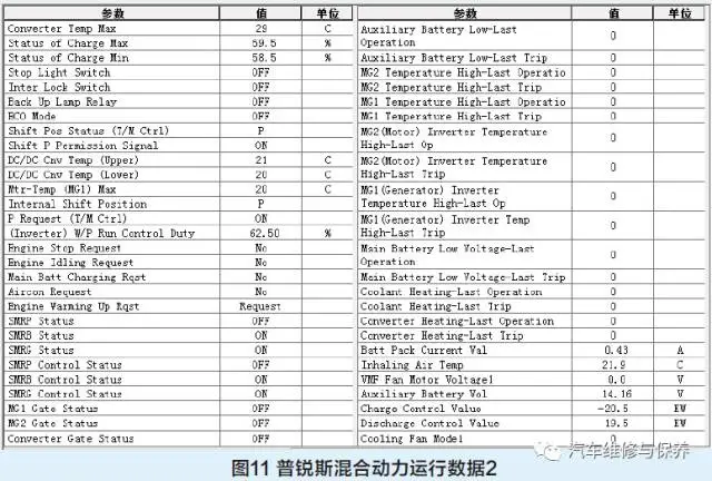

Figure 13 shows the engine start process data and MG1 running in the power generation state (when the engine needs to be started, MG1 outputs positive rotation speed, and the positive torque runs as a motor to start the engine. After the engine starts, MG1 outputs positive rotation speed and negative torque runs as the generator).
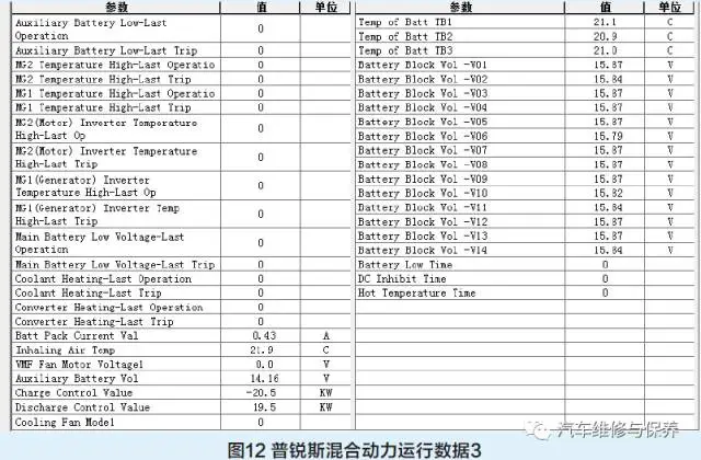
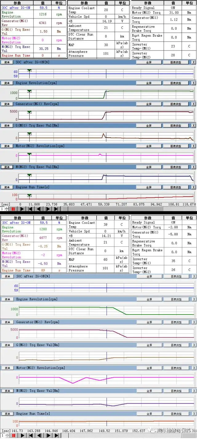
Figure 13 Prius engine starting process data
3. Explain the function of solving angle transducer. Solution angle transducer is used for magnetic field directional control when MG1 and MG2 motors are running, so that the motor outputs a constant torque below the rated speed and maintains a large power above the rated speed. The structure of the solution angle transducer is in the form of a resolver. It consists of field coils, detection coil S, detection coil C and an oval rotor (rotating together with MG rotor as a unit). The S and-S of the detection coil S deviate from each other by 90℃. The C and-C of the detection coil C also deviate from each other in the same way. The coils S and C are separated from each other by 45℃. When constant frequency AC input field coils, with the rotation of the elliptical rotor of the resolver on the motor rotor shaft, the gap between the resolver and the stator changes, therefore, the constant frequency induced electromotive force is mutually induced in the detection coil S and C. MG ECU calculates the absolute position of the main magnetic pole on the rotor by using the peak difference between the coils S and C, and calculates the rotation speed according to the variation of the rotor position within the specified time.
4. Regarding the steps of starting the engine strongly and activating the vehicle maintenance mode, the article does not write in detail, and the method is completed here. The method of not using intelligent detector is as follows:
(1) in 60s, perform the following steps (A) to (D) and place the power switch in the ON(IG) position (step A).
(2) when selecting the parking stop (P), completely press the accelerator pedal twice (Step B).
(3) when neutral (N) is selected, completely press the accelerator pedal twice (Step C).
(4) when selecting the parking stop (P), completely press the accelerator pedal twice (step D).
(5) check and confirm that the "maintenance mode" is displayed on the multi-information display screen ".
(6) when pressing the brake pedal, start the engine by placing the power switch at the ON position.
Note: When parking block (P) is selected, the idle speed in maintenance mode is about 1000r/min. When parking stop (P) is selected, the engine speed increases to 1500r/min when the accelerator pedal is pressed. When the accelerator pedal is pressed more than half or the accelerator pedal is completely pressed, the engine speed rises to about 2500r/min.
5. Regarding safe operation, the author wrote very clearly in the article, and it should be emphasized that when replacing the inverter with booster converter, the installation of components and the tightening torque of wires must be operated strictly in accordance with the requirements of maintenance manual.