
Failure phenomenon
A 2013 Volkswagen Jetta car with a carrier Number of BJG engine. The exhaust emission indicator on the instrument gives an alarm, but there is no abnormal feeling during driving.
Fault diagnosis and remove
First, use VAS5051 to query that the fault code 16724: CMP camshaft position sensor A circuit is incorrectly configured in the engine ECU. In the idle state, the data of Zone 3 and Zone 4 of 01-08-12 group is read and displayed as 0 (the normal values should be 28 and 87 respectively), zones 3 and 4 indicate the corresponding relationship between the crankshaft position signal and the CMP camshaft position signal, in short, the relative position identification between the high and low points of the signal Cam and the crankshaft position reference point. Both zone 3 and zone 4 are displayed as 0, indicating that engine ECU cannot recognize Cam G signal and curved position Ne signal.
Incorrect camshaft timing position or sensor line failure will cause the CMP camshaft position sensing value received by ECU to be incorrect and the fault will be reported (if G40 is disconnected, the same fault code will be reported). For this reason, first check that the engine valve timing is normal. Since the probability of mechanical failure of camshaft itself is too small to be ignored, the investigation idea can be determined as the evaluation of sensor line failure.
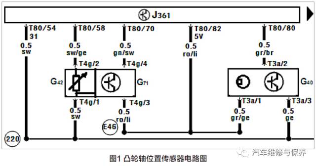
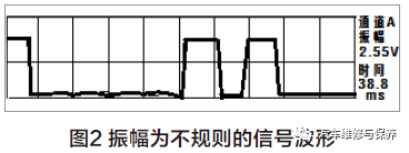
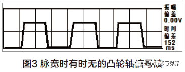
According to the 2013 Jetta BJG engine Jetta CMP camshaft position sensor circuit diagram (Figure 1), The T3a/1 foot of the CMP camshaft position sensor G40 is the power supply terminal, and the T3a/3 foot is the internal iron terminal of the ECU, t3a/2 feet connect the T80/80 feet of ECU to provide feedback signal voltage to engine ECU. Using the waveform detection tool of VAS5051 detector, the measured T3a/3 feet and T3a/1 feet have 5V power supply voltage and normal grounding, and then take the T80/80 feet of ECU as the monitoring point, the measured waveform amplitude is 2.55v irregular signal waveform (Figure 2), the pulse width is sometimes absent, and occasionally the waveform amplitude is 2.55v camshaft signal wave (figure 3), however, the normal G40 signal waveform is a square wave whose amplitude is 5V with continuous periodic variation, and the detection shows that the sensor signal is distorted.
According to the observation that the waveform has no abnormal interference and abrupt changes, it is not likely that the line transmitting camshaft signals will fail or be affected by peripheral electromagnetic interference, so far, the fault source can be locked on the engine ECU and the CMP camshaft position sensor, and the functional detection should be carried out respectively. Disconnect the G40 plug, take T80/80 feet T3a/2 feet connected to the engine ECU as the detection point, and measure the linear voltage output by ECU on the ignition gear to 2.5V, the signal voltage of the normal vehicle is 5V by contrast measurement.
CMP camshaft position the sensor is a hall device, which can be regarded as a state switch with on and off functions. The disconnection of the line simulates the CMP camshaft position of the off condition sensor, the signal voltage of off condition directly reflects the state of starting ECU T80/80 feet. From this, we can analyze and infer that the signal processing module of ECU has circuit failure and the reference voltage provided has problems, the fault storage code 16724: CMP camshaft position sensor A circuit is incorrectly configured. This fault code belongs to the alarm category of exhaust emission indicator light in the alarm mechanism. The failure of this signal can be calculated by using the signal of motor speed sensor G28 instead, and the fuel injection and ignition sequence of the cylinder can be vaguely identified, so as to realize ECU emergency driving condition, because other executive components work normally, from the driver's feeling, it is not felt that the fault has obvious influence on driving condition.
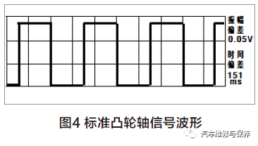
After the engine ECU is replaced, the camshaft voltage signal is measured, which is the standard waveform shown in figure 4. The amplitude is normal 5V, and the exhaust emission indicator light is no longer alarming, and the fault is completely eliminated.
The fault is not complicated in terms of fault mechanism, mainly because the internal circuit fault of the engine control unit causes the sensor 5v reference voltage to be too low. Under The G40 working state, the peak value of break-over voltage is lower than the internal set value of the computer, so that the engine computer cannot correctly identify camshaft signals. The causes of this kind of failure generally include sensor body failure, line failure, engine control unit failure, etc. The judgment of this kind of fault should first check the relevant lines of G40 according to the requirements of maintenance manual, which includes the basic inspection of G40 Ground, 5V voltage and sensor signal voltage. According to the author, when measuring the T3/a signal voltage, we can find the abnormal situation that the voltage is only 2.5V, which indicates that the Hall voltage of the engine control unit is abnormal. Before that, the author adopted the waveform detection method to observe the abnormal signal waveform more intuitively, and then combined with the detection of relevant circuits to judge that the fault occurred in the engine control unit body.
This method of detecting and diagnosing vehicle faults with the help of advanced equipment is a way that our automobile maintenance industry has been advocating and promoting, and it is also an advanced method for fault diagnosis of modern vehicles, however, due to the fact that most domestic maintenance enterprises do not have relevant advanced testing equipment, they still use the replacement method to repair vehicles when judging similar faults, resulting in more manpower, the loss of material resources has increased the maintenance cost for customers. It has to be said that it is still very difficult to truly implement the guidelines of the Ministry of Communications on the diagnosis and detection of vehicles before maintenance.
Finally, the author's diagnosis process is explained. The whole diagnosis process, including the narration of the article, has a strong academic color. The narration of the article is clear and the diagnostic thinking is basically correct, it is worthy of recognition, especially that teachers from schools can achieve such a situation of vehicle failure, which is worthy of praise. I hope more teachers engaged in vocational education have stronger practical ability.