
Recently, a Cadillac car owner sent a WeChat inquiry to the author, the car combination instrument shows that the red "Battery Not Charging" and "Service Charging System" faults warning light are on (Figure 1), whether you can continue driving. The author told him that the warning message meant "the battery cannot be charged and the charging system can be repaired" and asked him to enter the store for repair as soon as possible. Because if the generator cannot charge the battery, the electric energy in the battery will soon run out, the spark plug cannot be ignited, and the engine will soon shut down. It is very dangerous to drive a car that can stall at any time on the road.
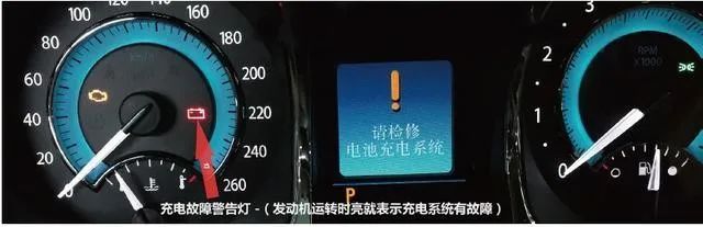
Figure 1 charging system fault alarm diagram sent by Cadillac owner
Combined with the failure phenomenon of the car, I would like to share with you the type, structure, principle and diagnosis methods and skills of the charging control system of Cadillac, Buick, Chevrolet and other general American vehicles.
I. New voltage regulation control system
The traditional charging system has built-in temperature sensor in the generator of the car, so as to establish the set voltage value of the generator. When the generator is in the cold state, the output voltage value set by the generator will rise; When the temperature of the generator rises, the set output voltage value will drop. Cars using this voltage-controlled charging system are prone to overcharging during long-time driving on expressways, but insufficient charging will occur during low-speed and short-distance driving.
The new voltage regulation control system is a new type of dynamic control system of vehicle system voltage. It mainly adjusts the output voltage value of the generator according to the estimated battery temperature and the charging state of the battery. It has the advantages of improving fuel economy, prolonging the life of the battery, prolonging the life of the bulb, prolonging the life of the switch, etc.
General Motors has begun to adopt the third generation of new voltage regulation control system (Figure 2), which is mainly assembled in Cadillac CTS, SRX and STS; Chevrolet and Chevrolet full-size trucks and multiple SUVs; chevrolet Cobalt and Uplander; Buick LaCrosse and Terazza; Pontique Grand Prix and SV6 and other new models.
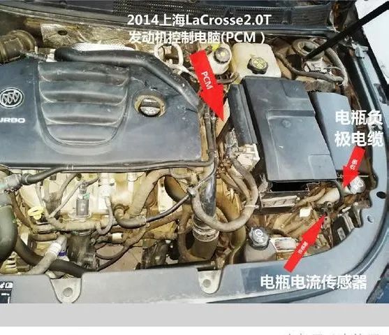
Figure 2 Buick LaCrosse generator voltage regulation control system
The new voltage regulation control system allows the vehicle voltage to fluctuate up and down within a certain range, which is generally 12~14V; While the traditional voltage regulation device usually requires the voltage to be stable at 14v.
II. Two types of common voltage regulation control systems
At present, common voltage regulation control systems in general motors include: Integrated voltage regulation control system (RVC) and standard-independent voltage regulation system (SARVC).
The integrated voltage regulation control system (RVC) collects the charging and discharging information of the battery through the battery current sensor and transmits it to the body control module (BCM). The system accurately measures the positive voltage of the battery and the circuit voltage where the ignition switch is in the OFF gear and the ignition switch is in the ON gear (the engine is not running).
When the ignition switch is OFF, the State Of Change (SOC) Of the battery is determined by accurately measuring the open circuit voltage. The state of charge is a function of the acid concentration and the internal resistance of the battery, which is determined by the estimation of the open circuit voltage during the static storage of the battery for several hours.
When the ignition switch is ON (the engine is not running), the calculation program continuously estimates the charging state of the battery according to the adjusted electric quantity (Ah value), battery capacity, initial charging state, temperature and other parameters.
During the operation of the engine, the discharge size of the battery is mainly determined by the battery current sensor. This sensor is used to collect the net Ah value.
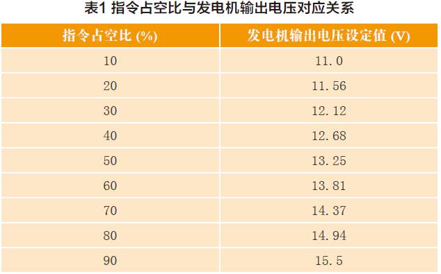
The body control module (BCM) exchanges information with ECM/PCM through serial data circuit about all kinds of useful information related to the battery related to the corresponding relationship between the duty cycle of the instruction in table 1 and the output voltage of the generator, the generator is directly controlled by ECM/PCM.
Standard-independent voltage regulation control system (SARVC) does not use body control module (BCM) to realize control. It is equipped with a generator and battery control module at the negative cable of the battery, which is used to collect and analyze the current, voltage, battery temperature and other information of the battery. The current sensor of the battery is set inside the module. The duty cycle of the generator L terminal is directly controlled by the engine battery control module, rather than by ECM/PCM.
Both of the above two voltage regulation control systems have correction functions, so that the storage battery can remain in the state of 80% for a long time.
III. Operation mode of voltage regulation control system
The following takes the integrated voltage regulation control system (RVC) as an example to introduce the operation mode of the voltage regulation control system. The basic operating modes of RVC include: charging mode, fuel economy mode, voltage reduction mode, start boost mode, headlight/rear windshield ice melting mode, battery vulcanization mode. The six modes of RVC system are all to keep the battery in a state of not less than 80% power for a long time, and at the same time to ensure the electricity demand of vehicle-mounted electrical appliances. In particular, not all RVC systems enter the above six operating modes.
PCM/ECM (generator and battery control module for full-size trucks) controls the generator by controlling the engine L circuit, the operating state of the generator is monitored by monitoring the duty cycle signal of the generator magnetic field circuit. The duty ratio is the pulse width signal (plus the adjustment of the pulse width), the voltage is 5V, and the frequency is 128Hz, which is expressed by 0 ~ 100% (Table 1). The normal duty cycle is between 5 and 95%, and between 0 and 5% and 95 to 100% indicates that the system has faults and needs diagnosis.
1. Charging mode
As long as any of the following conditions are met, the control module will switch to the charging mode.
● throttle percentage exceeds 90%, and fuel charge (injection controlled by ECM/PCM) reaches 21 G/s.
● headlamps are connected to high beam or low beam.
● wiper opening time exceeds 8s.
● engine radiator electronic fan high-speed operation.
● The rear window electric heating defrost function is enabled.
● The battery charge (SOC) is less than 80%. Only if any of the above items are met, the control module will slowly increase the voltage at a speed of 8 ~ 50mV/s to 13.4~15.5V (depending on the state of the generator at that time).
2. Fuel economy model
As long as the following conditions are met, the control module will enter the fuel economy mode.
● The calculated ambient air temperature is higher than 0℃ (32 ℃) and lower than or equal to 80℃ (176 ℃);
● The calculated battery current is greater than 8A, but less than 15A;
● The battery charge (SOC) is greater than or equal to 80%;
● The magnetic field duty ratio signal of the generator is less than 99%. In this mode, the target output voltage of the generator is 12.5~13.1V. As long as the charging mode conditions are met, the control module will exit this mode and enter the charging mode.
3. Voltage reduction mode
As long as the following conditions are met, the control module will enter the voltage reduction mode.
● The calculated ambient air temperature is higher than 0℃ (32℃);
● The calculated battery current is greater than-7A and less than 2A;
● The magnetic field duty ratio signal of the generator is less than 99%; In this mode, the output voltage target value of the generator is 12.9V. As long as the charging mode conditions are met, the control module will exit this mode.
4. Start the supercharging mode
When the engine starts, the control module will set the output target voltage of the generator to 14.5V and keep it for 30s.
5. Headlight/rear window ice melting mode
As long as the headlight is turned on (whether it is dipped headlight or high beam), the body control module will enter the headlight/rear window ice melting mode, and the output voltage of the engine is 13.9~14.5V.
6. Battery vulcanization mode
When the voltage of the battery is lower than 13.2V and lasts for 45min, the control module will enter the battery vulcanization mode. As long as you enter this mode, the control module will set the output target voltage value of the generator between 13.9~15.5V and keep it for 5min. Then, the control module decides to enter other modes according to the voltage requirements of the system.
The control module determines the charging voltage according to the battery power state. When the ignition key is in the off state, that is, when the vehicle is stopped, the system measures the battery voltage every 8 hours, and then estimates the battery power state according to the 3 times measured during 24 hours. If the ignition switch is in the ON position, that is, during the operation of the engine, the system will monitor the battery voltage in real time, and compare these voltage measurements with the battery temperature, so as to judge the battery state, it also determines the charging current and discharging current of the battery, and at the same time, the control module keeps the battery power above 80% all the time by adjusting the charging voltage.
IV. System hardware
1. Battery current sensor
Battery current sensor (figure 3) is a replaceable part located near the battery and connected to the negative electrode of the battery. Battery current sensor is a Hall effect sensor with three wires, which is used to monitor the current of the battery and directly provide the current signal to the body module BCM. The body module BCM generates a pulse duty cycle signal of 5V and 128Hz. When the system is normal, the duty cycle is between 5% and 95%.
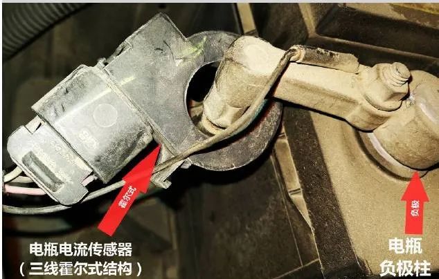
Figure 3 battery current sensor
2. Body Control Module (BCM)
The body control module (BCM) determines the output of the generator and provides information for ECM/PCM, while ECM/PCM controls the control circuit of generator L. The body control module BCM controls the actual output power of the engine by monitoring the magnetic field duty cycle signal from the ECM/PCM generator. In addition, it also monitors the battery current, positive voltage and temperature to control the charging state of the battery. The body module (BCM) also implements idle speed lifting and load management by executing or sending control commands to ECM or other controllers.
3. Generator battery control module
The generator battery control module is a replaceable part, located near the battery and connected with the battery negative cable. It directly controls the input signal of the generator magnetic field control circuit, monitors the generator magnetic field duty cycle signal circuit, monitors the internal current sensor, monitors the battery positive voltage circuit, and estimates the battery temperature so as to determine the charging state of the battery. Maintain communication with PCM, IPC and BCM to realize voltage regulation control function.
V. Diagnostic ideas of charging system
For each car, when the charging system fails, it should be diagnosed according to the specific structure and specifications of the charging system of the car. When encountering the fault code, you must check the maintenance manual of the car, to understand the exact meaning of fault codes.
When the charging system and battery are faulty, the combination instrument and information display screen of the vehicle will trigger the charging warning light to light up and display warning text information. The details are as follows:
● The ECM of the engine control module detects that the output voltage of the generator is lower than 11V or higher than 16v. Combination instrument will receive the information that the engine control module requires to light up warning light through GM local area network (GMLAN).
● combination instrument determine that the system voltage is lower than 11v or higher than 16v and the duration exceeds 30s, combination instrument will receive information that the voltage sent by the body control module BCM through GM lan is beyond the normal range.
● each time the ignition switch is turned on, the combination instrument will be tested for "charging warning light", and the charging warning light will light up for 3s.
If the charging voltage is kept at 13.8V all the time without changing with the load of the power system, this phenomenon may enter the default fault state, and the magnetic field control circuit of the generator should be detected at this time.
For the diagnosis of generator L terminal, the frequency block of multimeter can be used for measurement (for example, FLUKE 88V car special multimeter), or oscilloscope can be used for measurement. When the charging system works normally, the duty cycle measured by multimeter or oscilloscope is between 5% and 95%, and the specific value of the duty cycle depends on the mode of the charging system and the charging state of the battery.
The duty cycle signal of the integrated voltage regulation system (RVC) is the 5V pulse width reference voltage signal generated by ECM/PCM; Standard independent voltage regulation system (SARVC) the duty cycle signal is the 5V pulse width reference voltage signal generated by the generator battery control module, and this duty cycle signal is controlled by the generator itself for cyclic grounding.
If there is a fault in the charging system, we should not only pay attention to the fault codes related to the charging system, but also pay attention to the fault codes related to low voltage. Because when the charging system fails, these fault codes will be generated first.
If there is a fault in the charging system but no fault code is stored, the charging system should be tested according to the operating specifications and procedures in the maintenance manual. If the failure point is still not found, further inspection is required through the road test.