
Car model: Q5 2.0T TIPTRONIC.
VIN: LFV3B28R4E3 ××××××.
Mileage:4 839km.
Failure phenomenon: Q5 engine EPC light is on.
Fault diagnosis: the customer of the car reported that the EPC light was on, and the diagnosis equipment detection fault code result: P157600, right electric hydraulic engine bearing solenoid valve, the earthing short circuit; P157200, left electric hydraulic engine bearing solenoid valve, the earthing short circuit; P044500, fuel tank exhaust valve, short circuit; P003400, turbocharger air splite-flow valve, the earthing short circuit; P2 0 0 9 0 0, intake pipe control (IMRC), the earthing short circuit; P164E00, engine oil pressure controlled valve, electrical failure; P104900, cylinder row 1, camshaft regulating valve, exhaust, the earthing short circuit; P105000, cylinder column 1, camshaft regulating valve, exhaust, open circuit; P152700, cylinder column 1, Camshaft adjustment, the earthing short circuit and other 20 faults. Check the circuit diagram and see that all components involved in the fault are powered by SB7 fuse, as shown in Figure 1.
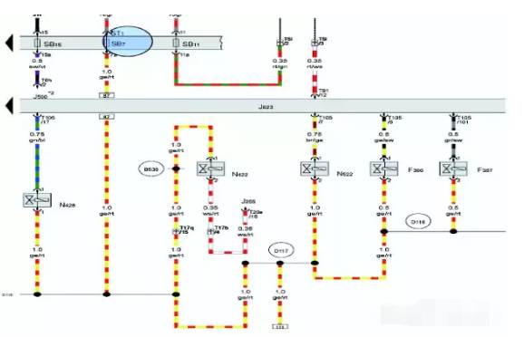
Figure 1 insurance SB7 control circuit
Check the fuse and find that it has been blown. After replacing the new fuse, it will be blown immediately, thus it can be judged that the SB7 fuse power supply circuit or electrical components have short circuit phenomenon. Remove the plugs of electrical components involved in the diagnostic record one by one, and determine whether the short circuit status of the circuit changes. After all the engine wiring harness plugs are removed, the short circuit phenomenon still exists. Remove the engine harness from the engine and place it on the workbench, as shown in figure 2. Connect the test lamp with the positive electrode of the battery, connect the test lamp to the SB7 load terminal, connect the negative electrode of the battery to the ground wire end of the engine wiring harness, and the test lamp will turn on to prove that the short circuit does exist.
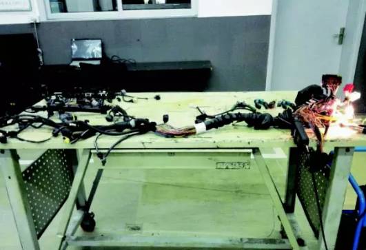
Figure 2 removing engine wiring harness
The VAS6356 of the current clamp oscilloscope is used for section-by-section investigation. Finally, it is found that the fault point is near the wiring harness of the ignition coil. The wiring harness is bent carefully and checked carefully. It is found that the test lamp will be temporarily extinguished occasionally, indicating that the fault point is in this part. Tear down the wiring harness of ignition coil and find that there is contact between internal power supply and ground iron, as shown in figure 3.
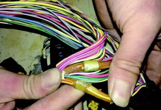
Figure 3 short circuit
Failure summary: from this, it can be concluded that the fault is caused by poor insulation of the positive and negative nodes in the wiring harness and insulation glue softening caused by high temperature of the engine. Under Vibration and extrusion, the nodes are in contact with each other for short circuit, resulting in fuse fusing and causing a series of faults, it is suggested that manufacturers improve the production process, insulation the nodes or separate them so that they can not reach them, so as to eliminate hidden troubles such as short circuit and even line fire.